Helium Recovery from Natural Gas
Helium Sources.
Helium is present in atmospheric air at 5.2 ppm. It is uneconomic to recover this except perhaps in the very largest air separation plants. Fortunately, Helium may also be present at fractions of a percent up to a few percent (rarely) in natural gas and this represents a valuable and essentially a depleting resource. Helium capture from natural gas is usually as a co-product from cryogenic processing of the natural gas for other purposes. These are liquefaction of the natural gas, and nitrogen removal from the natural gas to increase its heating value. Recently, some sources of helium have been discovered that are rich enough (several percent) to justify processing the gas purely for the value of the helium content.
But before focusing on helium recovery a few words on the associated gas processing steps of Liquefied Natural Gas (LNG) and Nitrogen Rejection Units (NRU) are appropriate.
LNG – Liquefied Natural Gas
LNG base load at high capacity is mature technology, the main supplier and technology being APCI’s mixed refrigerant (MR) process. The produced LNG is stored at 112K (-161 C) and shipped in huge cryogenic ocean tankers to the customers location where it is unloaded and ‘regasified’ i.e. heated to restore to natural gas. for use by consumers and industry
Mid-scale and flexible capacity LNG technology is still evolving. Turbo-expander cycles using natural gas and/or N2 are simpler than MR.
Small scale eg bio gas sourced LNG – here the focus is on simplicity to reduce cost at the expense of efficiency.
For production of LNG the major power consumer is the refrigeration compression. How will this be supplied? New power plant or Gas Turbine (GT) or Gas Engine (GE) drives? The answer depends on the scale. Typically multiple trains of gas turbine drives would be provided for the compressors on a base-load LNG plant.
LNG Process Features Overview
After feed pre-treatment to remove freezable components such as water and CO2, the feed gas and the HP refrigerant are cooled in the main heat exchangers (BAHX or spiral wound type) against the countercurrent vaporising and warming refrigerant streams.
High pressure feed natural gas also reduces the energy required for liquefaction for 2 reasons :-
a) it reduces the enthalpy of the NG feed, and therefore the total refrigeration load
b) it makes the enthalpy vs temperature cooling curves more nearly linear and parallel. This facilitates an overall close temperature approach, even with an expander-based process. This in turn reduces the irreversble entropy generated in the heat exchange which has a direct impact on the required power input.
In some designs, the purified natural gas and the refrigerant are one and the same, and can therefore share the same compression system. (This is supplemented by the expansion turbines-driven brake compressors.)
The cold-end pressure reduction – partly by turbine and part by J-T expansion produces some flash vapour streams. After separation they may be warmed to assist feed cooling and then passed to fuel, and/or may concentrate the light components N2 and He for subsequent processing to concentrate helium.
NRU – Nitrogen Rejection from Natural gas.
Nitrogen rejection from Natural gas is a mature proven cryogenic process, analogous to the ASU double column where LP and HP columns are thermally coupled by a condenser/reboiler. eg NRU plant at Odolanow, Poland.
This process is used for medium to high feed N2 content (>30%) and needs little or no external refrigeration, as all products are gaseous, hence relatively low power demand. In fact the main energy required by the separation derives from the high pressure feed and the relatively low pressure of the rejected N2 product. The methane can usually be delivered at intermediate pressure and boosted externally in a ‘sales gas’ compressor if required.
This process can handle lower N2 content by addition of a pre-separation column to remove some CH4 product upstream of the double column. - as used in the Hannibal plant, Tunisia.
If present, Crude Helium is recovered via a purge from the HP column condenser. The further He concentration, purification and liquefaction steps are proven technology but may be modified depending on the presence and amounts of impurities such as H2 and Ne.
NRU – from LNG
Nitrogen removal from LNG is required typically to reduce N2 below 1% to avoid potential operational instability of LNG in storage, and it turns out that this step facilitates recovery of any helium present in the raw gas.
Normally N2 is removed in the vapour from the ‘end-flash’ vessel. This stream takes away most of the N2 together with some CH4 and is used as fuel. Adding a reboil coil to the vessel enables a more thorough N2 removal from the liquid phase before it passes to LNG tank.
The flash / stripped vapour can first be concentrated in N2 (and therefore helium) by adding trays or packing and reflux. Increasing the flash drum/stripper pressure raises the temperature of the reflux stream (less cold refrigerant). LNG and/or Liquid Nitrogen (LIN) can be considered as refrigerant for this step.
Helium Capture
Helium is much more volatile than N2 and CH4 and is concentrated in the end-flash vapour of an LNG plant. It may be concentrated to 45 to over 80% He by the cooling and partial condensation of most of the N2.
Helium Purification
Liquefaction of helium requires thorough removal to below 1 ppm of all impurities. The residual impurities are primarily N2 plus small amounts of CH4, Ar, O2, Ne, H2.
Apart from Ne and H2 these are removed together with N2 by partial condensation. Nitrogen evaporating under a partial vacuum (ca 0.2 bara) at about 66K (-207°C) concentrates the crude He to 98%, the balance being N2+Ne and any H2. This is followed by adsorption – either at low temperature (as in Odolanow) or by PSA, before passing to the helium liquefier unit.
The Polish natural gas contained about 100 ppm H2 which concentrates to over 2% in the crude helium. H2 is effectively removed by catalytic combustion, with air or oxygen, but this does require the cold crude helium to be first warmed to ambient and then preheated further to initiate the reaction. The H2 free helium is dried, (to remove the water formed by oxidising the H2 and any water in the small oxidant air stream and CO2 removed by adsorption and then re-cooled for the final purification steps as described above.
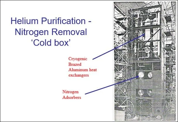
Odolanow Helium Purification cold box before closure and filling with insulation.
One issue for the catalytic combustion is to ensure there is no significant CH4 impurity as this can raise the reactor temperature (subject to sufficient O2) and potentially reduce the effective H2 removal.
This indicates a more stringent separation of CH4 from the crude helium (He plus N2) when recovering from the LNG flash gas. This is readily achieved with the Odolanow-type double column process, by employing some ‘pasteurising’ trays at the top of the HP column to wash down CH4, but it adds some complexity to the process of enrichment of LNG flash gas sourced Helium.
Some helium bearing gas may have only a few ppm H2 which would concentrate to a few hundred ppm in the helium-rich stream. Consideration should therefore be given to alternative hydrogen removal strategies to catalytic combustion – such as low temperature adsorption prior to feeding the liquefier or within the liquefier. It is normal to include one or more guard adsorbers within the liquefier. Such an adsorber is advisable anyway to remove traces of Neon often present at ppm level in the helium.
Note:
Membrane technology has been mooted for He enrichment. This has been proven in Alberta, Canada in the late 1970s, but for recovery from LNG a cryogenic route appears more suitable. (See upcoming article on membranes).
Helium Liquefaction
This is complex but mature technology. Purified helium typically at 15-20 bar is pre-cooled to about 80K by heat exchange with liquid Nitrogen and then further cooled to 6-8 K - the refrigeration being supplied by two or more helium turboexpanders. A first J-T expansion may be used when the HP helium is near the inversion curve.
Polish Helium liquefier before inserting into vacuum casing.
After a final cooling stage Liquid helium is produced at near atmospheric pressure on final expansion into the storage tank either via a J-T valve or a dense phase expander.
The double walled LHe storage tank is elevated by 7-8m above grade and its vacuum space has a LIN radiation shield supplied from a small LIN reservoir. The inner vessel is typically surrounded by multiple layers of superinsulation or equivalent to minimise boiloff.
Road tankers would sit on a weighbridge whilst being gravity fed from the main tank. Boiloff and displaced vapour from the tanker returns to the static tank and thence back to the liquefier. All connecting lines would be vacuum jacketed with getters in the interspace.
Empty tankers returning warm and / or pressurised or with impure contents need special preparation before being filled.
A basic process design (heat and material balance) can be obtained using a process simulation program or be prepared by hand using thermodynamic tables.
However, the detailed design and fabrication of the vacuum enclosure and its contents - the cryogenic expanders, plate-fin exchangers, J-T valves and the vacuum storage tank should carried out by specialist suppliers having the relevant experience.