Cryogenic Refrigeration Part IV – Refrigeration by Work Expansion
Overview
The Joule-Thompson refrigeration system, described in a previous article, can be complemented and, in some cases, replaced by using a ‘work-expansion’ refrigeration process. In this process the high -pressure refrigerant fluid is not expanded isenthalpically through a valve, (throttled) but is used to drive an engine (typically a turbine) at high speed.
This process removes enthalpy from the expanding gas, the energy or work passing along the turbine shaft to drive a compressor or other form of brake at the other (warm) end of the shaft. A small unit would dissipate the work extracted by circulating oil via a cooler. On larger units it makes sense to use this energy to drive a compressor, which is typically part of the process.
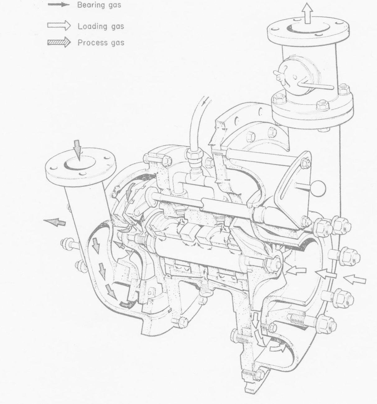
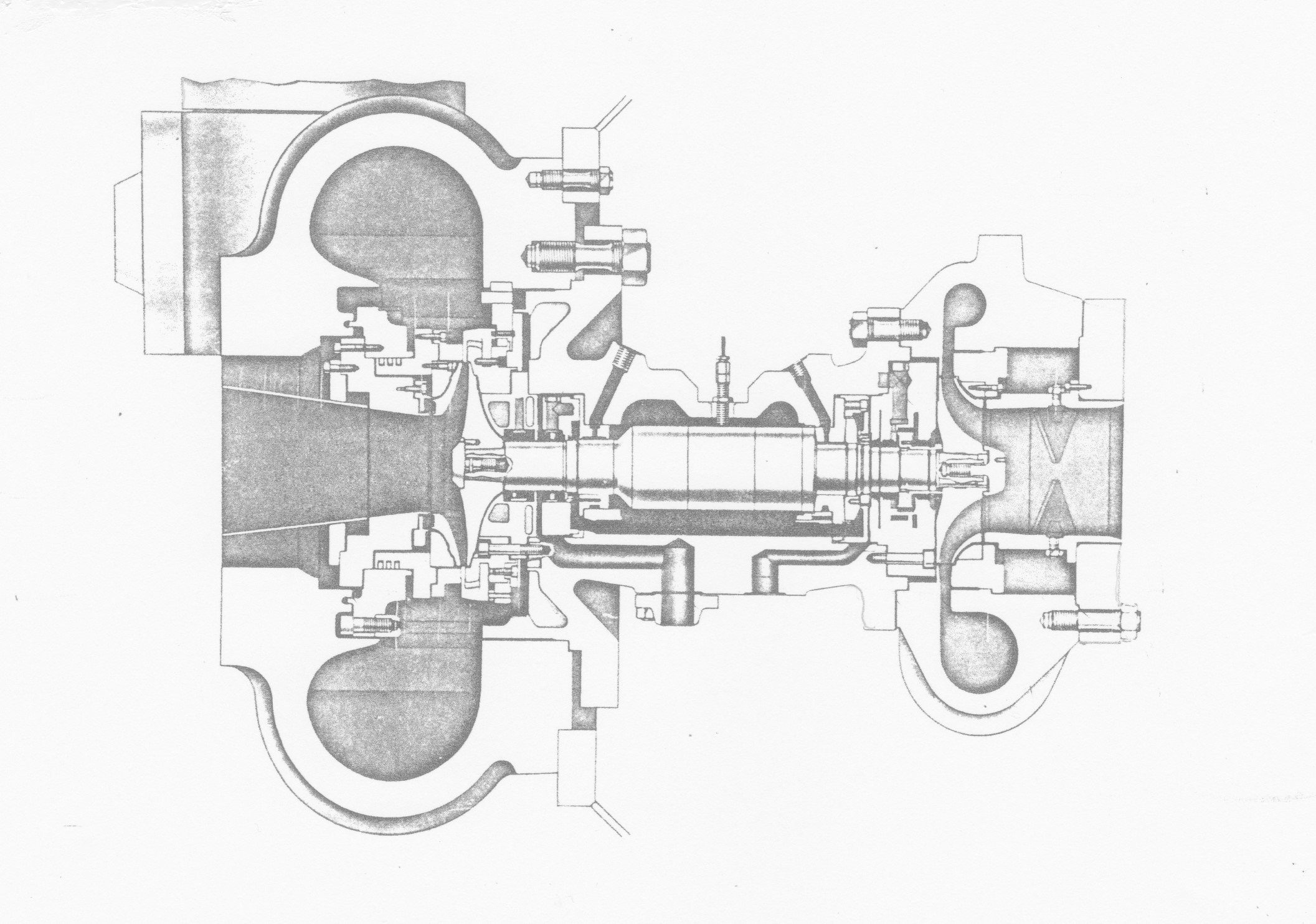
Gas-bearing turbine widely used on small air separation plants in the 1960s and 1970s. (Courtesy Lucas Ind.)
This approach to refrigeration or removal of heat energy does not depend upon the Joule-Thomson effect, and is therefore appropriate for liquefying the more ‘difficult’ gases hydrogen and helium. It is also used in the air separation process to provide more efficient refrigeration than J-T.
Entropy
To illustrate this process, we review the diagram of Temperature versus Entropy the so-called T-S chart in more detail. At this stage it is sufficient to define Entropy as a state variable which captures the degree of randomness or disorder of the fluid at the given T and P expressed as a logarithm. Qualitatively a fluid at higher temperature at a given pressure has a higher entropy than gas at the same pressure but lower temperature.
The molecules have more energy and there is more uncertainty or disorder or ignorance about their position or momentum, i.e. the entropy is higher. Conversely, a gas at high pressure and a given temperature is more ordered, than the gas at a lower pressure and the same temperature so its entropy is lower. A liquid has a lower entropy than a gas and a crystalline solid is lower still. As a fluid cools and condenses, their motion of the molecules becomes less random and as their temperature approaches absolute zero the entropy also tends towards zero.
The change (increase) in enthalpy ΔH, when a quantity of fluid is converted from liquid to gas (vapourised) or vice-versa is the latent heat often denoted by λ . The corresponding change in entropy ΔS is the latent heat, λ divided by the temperature T at which the vapourisation (or condensation) takes place.
ΔS = ΔH/T or ΔH = T. ΔS.
It is worth noting that in any real process there will be a net increase in the total Entropy of the system.
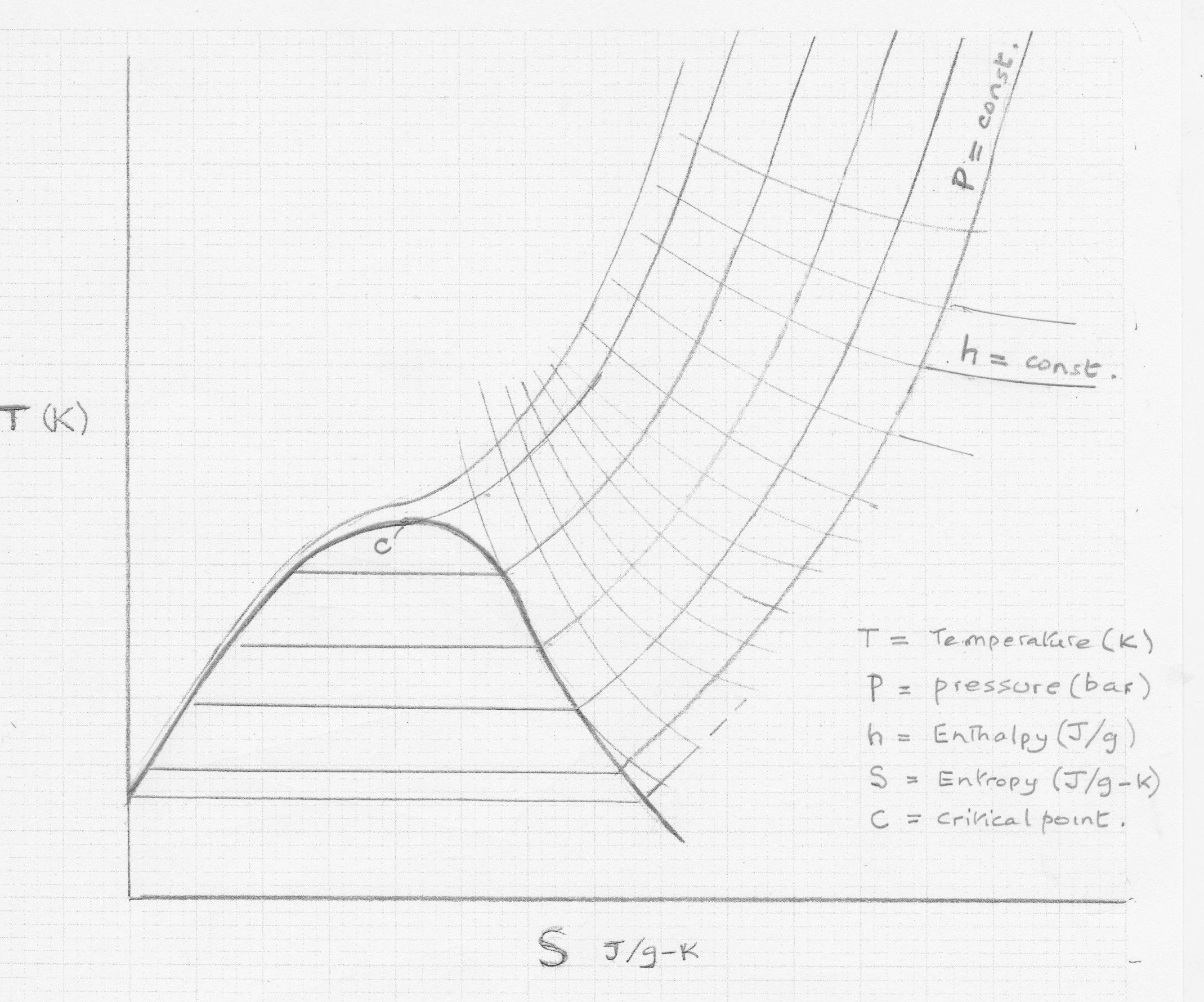
Generic Temperature Entropy Diagram
The T-S chart is an invaluable tool for the cryogenic engineer. The above chart is generic but is similar in form for all pure cryogenic substances, and for some close boiling mixtures such as air.
When a pure gaseous substance is condensed or liquefied at a temperature T1 by removal of the latent heat (ΔH or λ), its entropy is reduced by an amount ΔS1 = ΔH/T1.
This latent heat can only be removed by heat exchange with a colder refrigerant steam.
The heat gained by the refrigerant is the same i.e. ΔH, but the refrigerant temperature T2 must be lower (recalling the 2nd Law of thermodynamics). Therefore, the entropy gain by the refrigerant ΔS2 = ΔH/T2.
Evidently ΔS2 is always > ΔS1, so there is a net increase in entropy .
Net ΔS = ΔH.(1/T2 – 1/T1);
Notes:
1) Temperature must be expressed in degrees absolute (Kelvin).
2) Here for simplicity we have used ΔH to mean the enthalpy flowrate or power which is the mass flowrate of the stream (m kg/s) x Specific enthalpy h (kJ/kg) giving kJ/s or kW.
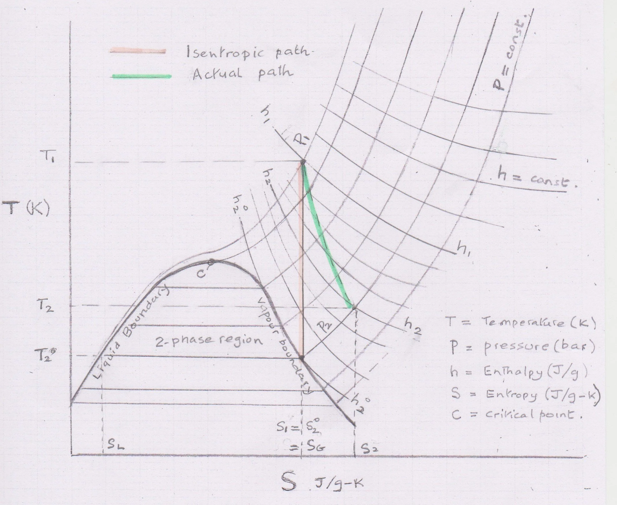
Work expansion - showing ideal (isentropic) and real path.
In this chart the points in a continuous process are enumerated: 1= inlet, 2= exit, and superscript So, ho etc refers to the exit conditions for an isentropic step.
The calculation of a Cryogenic expansion turbine can be done based on values read from the temperature entropy chart. Beginning from the inlet temperature and pressure a vertical isentropic path to the exit pressure determines the outlet conditions enthalpy and temperature. The enthalpy difference between inlet condition and outlet condition is the isentropic (ideal) delta H which would correspond to a perfect turbine. In practice an efficiency correction is applied usually in the range of 80 to 85% which then gives the actual enthalpy drop through the turbine. The corresponding turbine outlet enthalpy then determines the exit temperature at the specified outlet pressure. The delta H (kJ/kg) multiplied by the flow (kg/s) gives the power (kW) exported down the turbine shaft.
The calculation using a T-S chart is not difficult, but it is not very accurate. More precise calculations would use a process simulator such as HYSYS or UniSim.
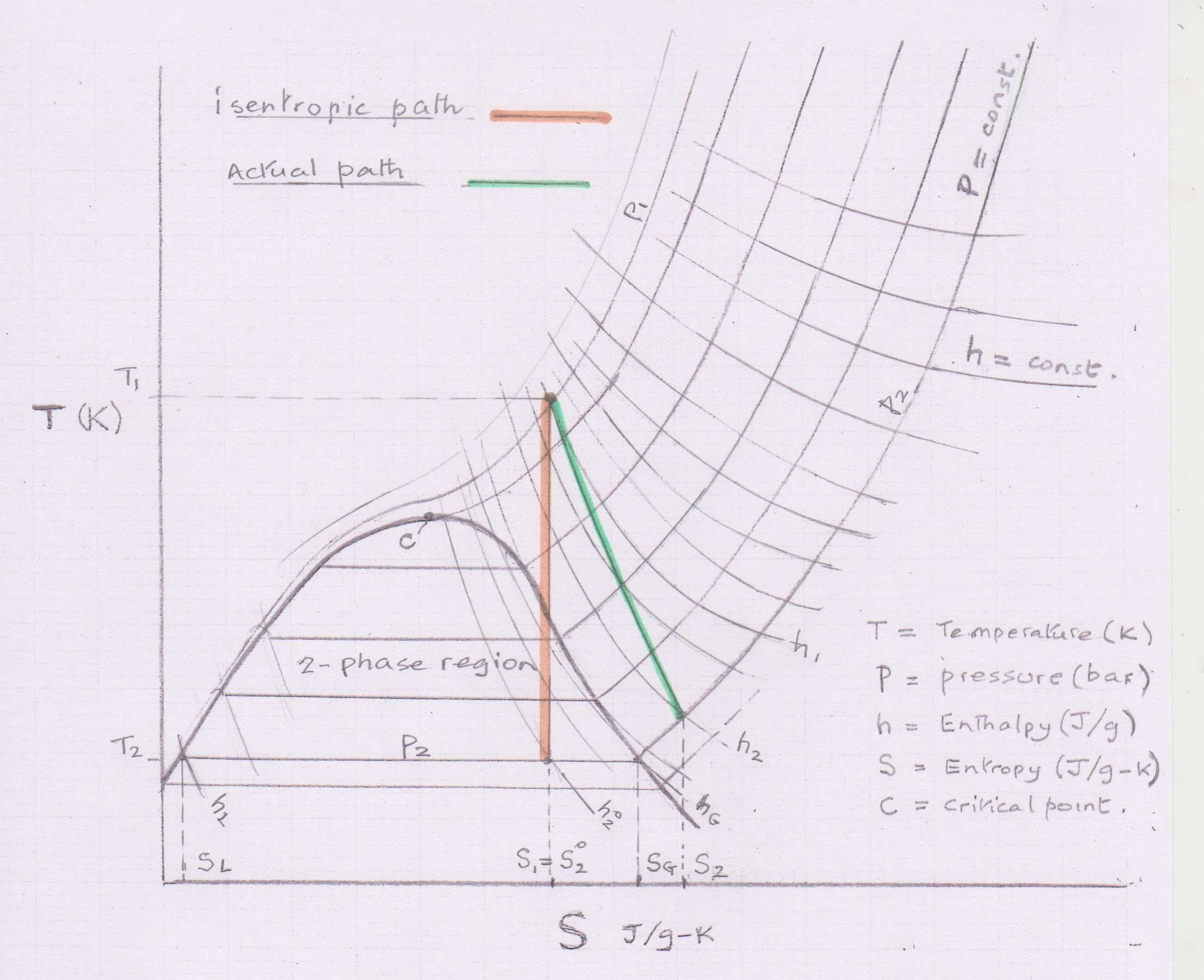
Alternatively, the author has developed an automated method using MS Excel with REFPROP from NIST to generate thermodynamic properties at the defined conditions. Results are expected to be accurate, but a special approach is needed when the isentropic exit condition drops into the two-phase region. The actual exit conditions can be either superheated vapour or 2-phase liquid and vapour.
‘Wet’ two-phase exit on isentropic expansion on isntropic expansion
The REFPROP-based Excel algorithm used will be described in a separate article.
Turbines to handle either gas or a mixture of gas and liquid were developed by Judson Swearingen at the company Rotoflow in the USA. Many other companies worldwide now offer cryogenic expansion turbines.
Nitrogen Expansion Turbine - (Courtesy Atlas Copco GB Ltd)
With the constant drive to improve the efficiency of cryogenic processes, attention has turned to the recovery of energy when expanding liquids from high pressure to a lower pressure within the process. This can be carried out with either a rotary or a reciprocating expansion ‘engine’.
This liquid expander is found worthwhile in large baseload LNG plants and in the largest air separation units. The benefit derives mainly from improvement in the process efficiency by reducing flash gas rather than power recovery which is relatively small.
Summary.
This four-part article has reviewed at a high level the main methods used to provide the refrigeration needed to keep a cryogenic process plant running at steady state.
Mechanical vapour compression, Joule-Thomson and Work expansion have been described with the help of generic versions of common thermodynamic diagrams, P-H and T-S. It is noted that some cryogenic plants may use all 3 types or refrigeration in combination, each providing ‘cold’ at different temperature levels where they are most effective.

